HDMI Specifications and Technical Info | HDMI Voltages, HDMI Wire Layout, HDMI Channels DDC, TMDS and CEC
Introduction
HDMI has emerged as a standard for high-definition audio and video transmission, and has increased in popularity on platforms such as the following:
- High definition television
- Digital video recorders (DVR)
- Set-top boxes (STB)
- High-resolution personal cameras
- Surround sound audio systems
As multimedia content has grown in popularity, HDMI hardware requirements have been included to ensure that data/power remains within regulation.
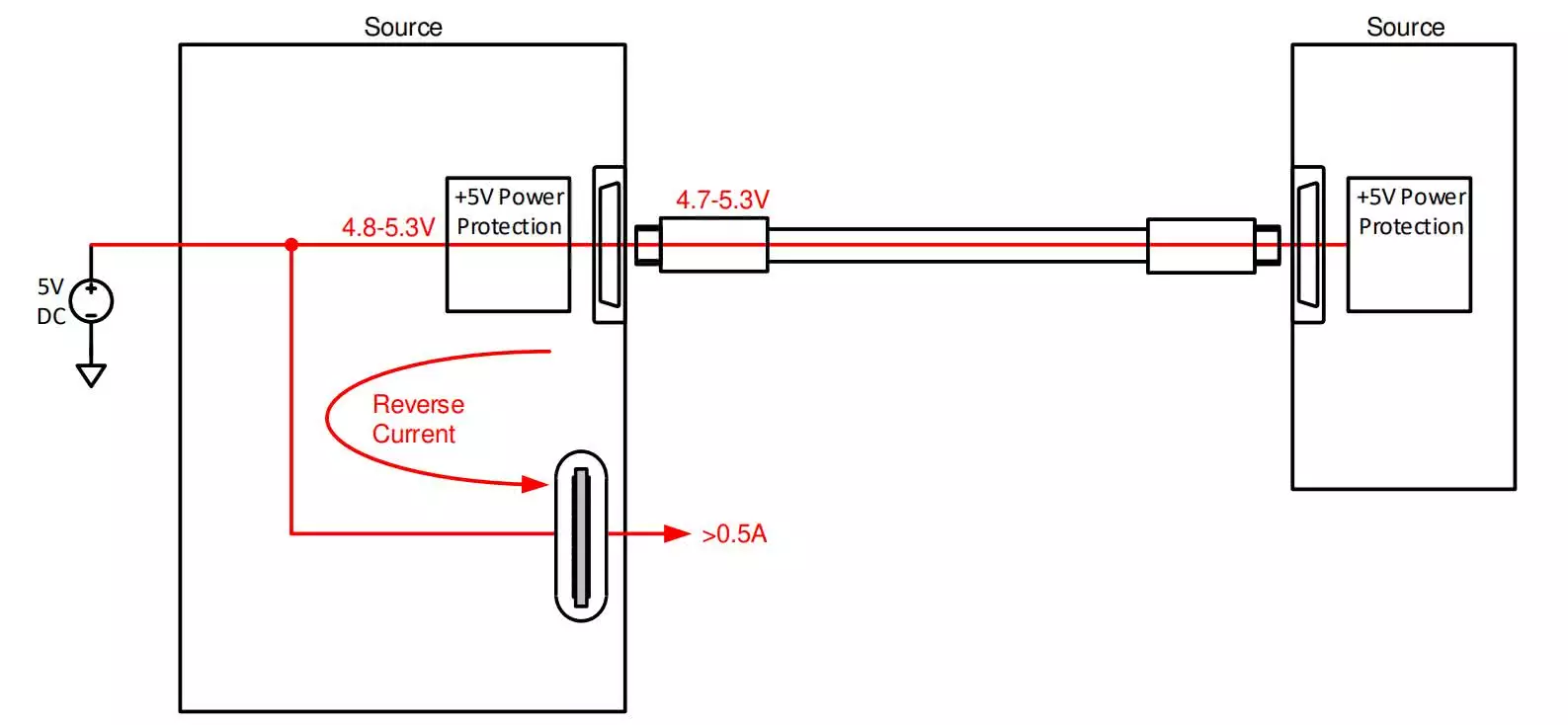
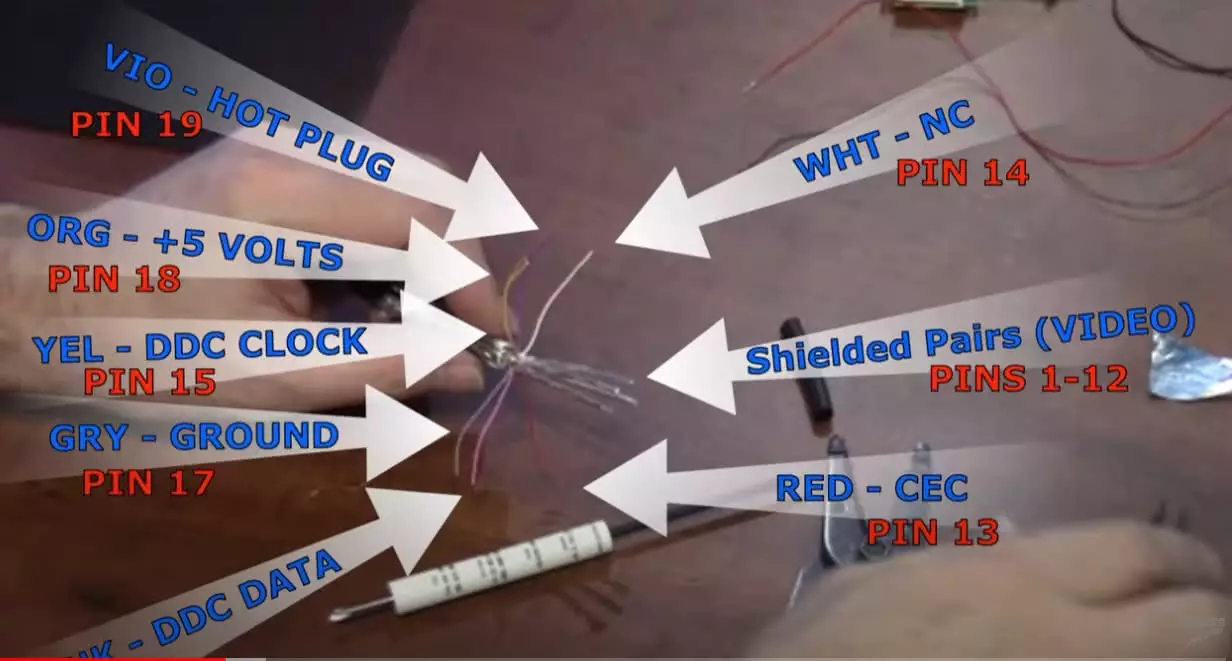
HDMI Ports must be designed on the 5 Volt DC Specification on Pin 18 (Orange Wire but wire color differs from some manufacturer). The HDMI Spec allows a tolerance of ±0.3 Volt in the spec as per picture below and will sync between 4.7v to 5.3v. Long Cable runs can influence voltage transmission if the source voltage are too low and maximum cable runs will differ from one HDMI port to another due to small HDMI Voltage fluctuations. Using ANY additional contact points such as a HDMI Coupler can reduce HDMI Voltage and results in no signal transmitted. HDMI Couplers in general are used on short distances and on long distances rather use an HDMI Equalizer / Booster.
In general Bi-Directional copper HDMI Cables WITHOUT a built-in HDMI Booster / Equalizer can be tested with a HDMI Tester. Copper HDMI Cables with a Booster / Equalizer is unidirectional (Indicated on Cable with Source / Display per Head) and some HDMI Tester channel tests may fail on a working cable. The same applies to Fiber HDMI Cables which cannot be tested by certain HDMI Testers since they do not follow the 19 to 19 pin rule as with standard copper HDMI Cables.

HDMI Compliance Requirements
In order to ensure a robust HDMI power design, the power rail needs to be regulated in the event of a transient condition. The HDMI 2.1 spec provides full detail of the 5 V regulation requirements.
In summary:
The basic requirements for an HDMI source are:
- Output voltage: 4.8 Vmin, 5.3 Vmax – In some case 5.3V may be ideal for longer cable runs to compensate for voltage attenuation over longer distances.
- Short Circuit Current: no more than 0.5 A
- Shorting two HDMI Sources together shall not result in any damage
- A sink shall:
Not draw more than 55 mA from the power signal when powered on
Assume any voltage within 4.7 V and 5.3 V indicates a source is connected.

Note:
No damage to the HDMI source or sink can result from the shorting of any combination of signals on any connector. If two HDMI sources are connected together with a single cable, no damage can occur to either of the sources. If two HDMI sinks are connected together with a single cable, no damage can occur to either of the sinks.
Based on these requirements, an ordinary 5 V regulated supply cannot be used. The 5 V power rail must be protected, whether connected to a source or a sink. Depending on whether the HDMI source is connected to a source or a sink, certain transient events can arise.
During the event that the output is connected to an HDMI sink, a potential short can occur along the output path. If the output is not regulated, a short in the cable can cause excessive heat dissipation that can damage the system and create a fire hazard. The 5 V HDMI source needs to be regulated such that if the output line is shorted anywhere to GND, the device can protect the system from the overcurrent event.
Source to Sink Output Protection
If two HDMI sources are accidentally connected together, the system must protect against any damage to either output. One condition that can arise is a reverse current condition. Since the HDMI voltage specification allows for the output port voltage to be between 4.8 V–5.3 V, there is the possibility that the downstream source is a higher voltage than the upstream source. In this condition, reverse current can potentially flow from the downstream source to the upstream source and damage upstream components.

The second condition that can arise when connecting two HDMI sources together is an output short to GND. Please ensure both devices are turned off when connecting HDMI Cables, If one source is OFF, there could potentially be an output short to GND which can damage equipment. The 5 V HDMI Protection device must ensure that the system remains protected in this configuration.
PTC and HDMI Surge Protection
There is another way to protect the HDMI port, and that is with a positive temperature coefficient resettable fuse (PTC). There are still several draw backs, such as a slower response time and degradation after resetting. PTCs operate by increasing the on-resistance as temperature increases but will provide additional protection on equipment. The temperature increase happens during an overcurrent event, but because the response of the PTC is based on this temperature rise, their response time is limited to several milliseconds
HDMI Surge Protection Dongles can be found at HDMI Surge Protection
Long HDMI Cable Runs and HDMI Channels : CEC, TMDS, DDC, Voltage Attenuation
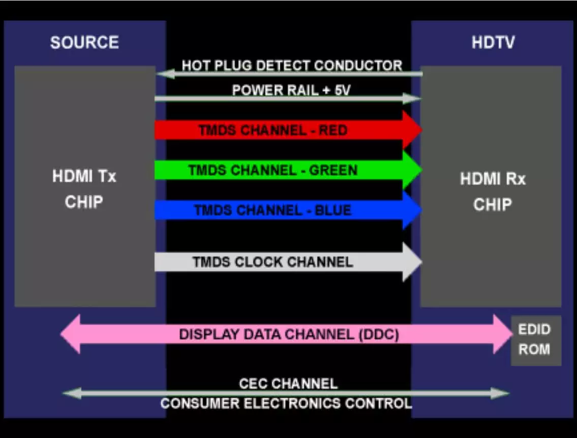
HDMI signals are carried through a cable with 19 discrete conductors (or wires). Two of those conductors represent the Display Data Channel (DDC) which is sometimes referred to as the I2C bus (See diagram and Wire Layout Below). The DDC supplies the HDMI source with the TV’s Extended Display Identification Data (EDID) which is stored in the display’s ROM …basically the display’s resolution capabilities along with other vital audio/video information the source needs. The DDC is bi-directional and also manages the HDCP “handshake” or key exchange that happens every 2 seconds as part of the authentication process between the source and the display. Signal attenuation caused by capacitance in long cable runs can adversely affect the exchange of critical DDC data causing erratic performance or in some cases, no picture or audio at all.

A HDMI Booster / Equalizer as at HDMI 4k Equalizer solves signal attenuation problems in HDMI applications where long cable runs are employed. It has an Adjustable Equalization circuit that helps overcome potential signal timing/delivery issues.
It also has DDC correction circuitry which helps condition the I2C bus to prevent data loss due to capacitance. This correction circuitry is extremely important for proper HDCP authentication in long cable runs. Finally, the 1391A is powered by an external power supply, which preserves the critical +5 volt rail so essential to stable performance in HDMI systems.
TMDS is “Transition Minimized Differential Signaling” which is the “pathway” for carrying digital video and audio signals, plus other needed data from point-to-point in digital circuits. There are 3 TMDS modes or channels of signal information sent in HDMI transmissions, plus a TMDS Clock to govern the speed or rate of the signals so that there are no timing or synchronization problems.
CEC means “Consumer Electronics Control” and is a one-conductor, bi-directional, serial bus that allows a person to control multiple CEC enabled devices with a single remote control. It also allows a CEC enabled device to control other CEC devices without any user action.
HDCP is an acronym for “High-bandwidth Digital Content Protection” which is an encryption process embedded in source material used to protect digital material from being perfectly copied. HDCP was approved for use by the FCC in August 2004 to protect the rights of authors, artists, and moviemakers under the auspices of Digital Rights Management (DRM), and the Digital Millenium Copyright Act.
HDMI Wiring Layout : May Differ from Different Manufacturers
